Flash Write Protect
1. Overview
In actual projects, when Kernel is started, many partitions are read-only partitions. But they can modify the partition through the mtd device or the partition is abnormally modified due to some uncertain factors, which will cause the system to fail to boot. Therefore, the user interface of Flash Write Protect is newly added.
2. Usage
-
Kernel Config disable the Write Protect function by default, and needs to be enabled manually:
NOR:CONFIG_SS_FLASH_ISP_WP
NAND:CONFIG_SS_SPINAND_WP
Note: Only one can be enabled at the same time.
-
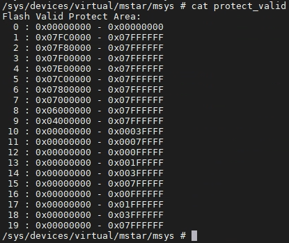
Read and write the protect and protect_valid files under
/sys/class/mstar/msys/to realize the operation of Flash Write Protect:Obtain the current Flash protectable section information:
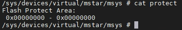
Set the current protection area:

Get the current protection area:
3. Preparation Guide
3.1. Principle
The Write Protect function of Flash can be realized by setting the register of Flash, and the operation method can refer to the Datasheet. The Write Protect functions supported by Flash of various manufacturers are different, but the basic protection functions are similar.
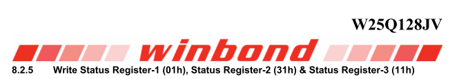
Take W25Q128 as an example, its Write Protect function is realized by writing bit 6: bit2 of Status Register 1:

Read and write Status Register 1:
Protection area corresponding to each bit value:

As shown above, WPS represents whether to use each block to set the Write Protect function separately. It is not supported by all Flash manufacturers, so our driver does not support the use scenario of WPS=1.
CMP represents whether to support the refinement of the function scope of Write Protest, which is not supported by all Flash manufacturers, so our driver does not support the use scenario of CMP = 1.
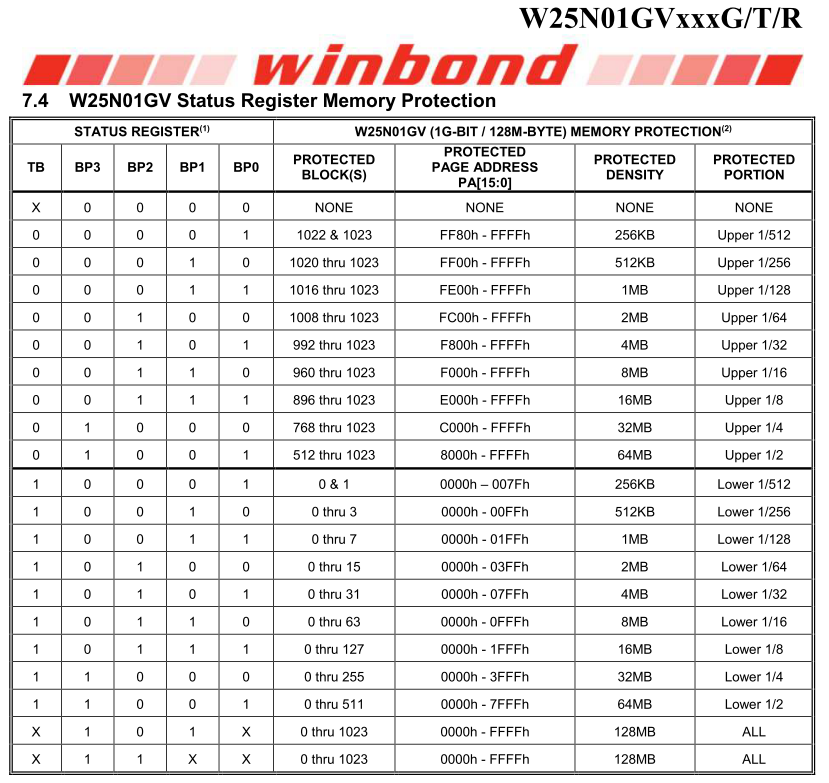
The principle of SPINAND is the same as SPINOR, only the registers read and written by SPINAND and SPINOR and the commands sent are different, such as W25N01G:
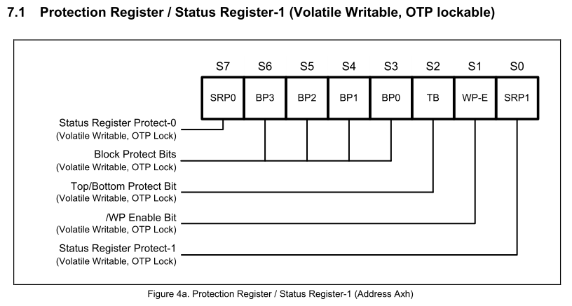
Read and write Status Register 1:


Protection area corresponding to each bit value:
3.2. Increase Driver Support
SPINOR Flash needs to add the pWriteProtectTable member of the _hal_SERFLASH_table array in drivers/sstar/flash_isp/drvDeviceInfo.c, which is the protection information of Write Protect:

_pstWriteProtectTable_W25Q128 stores the information of W25Q128 Flash Write Protect:
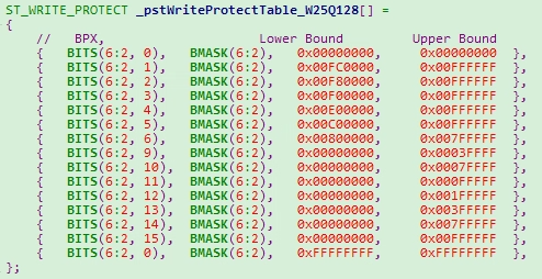
The first column of the array is the value of Status Register 1, the second column is the value's Mask, the third column is the low address of the protection range, and the fourth column is the high address.
SPINOR Flash needs to add the pWriteProtectTable member of the _gtSpinandWpTable in drivers/sstar/spinand/drv/mdrv_spinand_dev.c, which is the protection information of Write Protect:
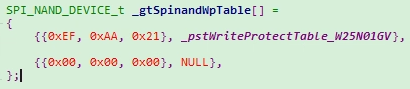
_pstWriteProtectTable_W25N01GV stores the information of W25N01GVFlash Write Protect:
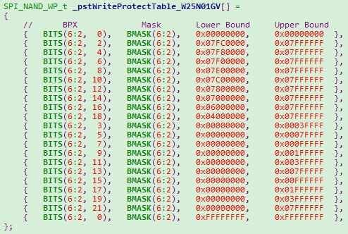
Note: u32LowerBound and u32UpperBound of the protect table must be 0xFFFFFFFF, which is a sign of the end of the array index.
The last item of the array of **_hal_SERFLASH_table and _gtSpinandWpTable is also a sign of the end of the array index, please do not modify it.
3.3. Set Boot Protection Area
Because it is difficult for the driver to know how the user application wants to set the protection area, the default protection area is set in Alkaid's compilation configuration. It is more reasonable to set different protection areas according to different partitions.
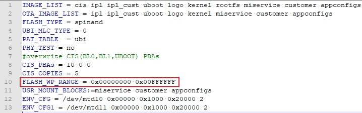
Add FLASH_WP_RANGE in project/image/configs/i2m/spinand.ubifs.p2.partition.wp.config: